Roarks Formulas for Stress and Strain Flat Rectangular Plate; one edge fixed, opposite edge free, remaining edges simply supported loading 2/3 of plate from fixed edge Stress and Deflection Equation and Calculator. Per. Roarks Formulas for Stress and Strain Formulas In order to improve the accuracy of FWD bending and vibrations of simply-supported beams and plates.
The curving or deflection of plate perpendicular to the plane of cross section of plate when subjected to a load is called as bending of plate. Calculate Deflection for Hollow Rectangular Beams. If you change any unit types or values please press SOLVE again. PL = Point Load. Displacement Notice that the deformation is axial symmetric and it is only a function of the radius. Determine the deflection at the load point as a function of the number of elements used per side to model the plate. Theo- Plates provides deflections and stresses in loaded circular disks and rings with; six edge support options and four possible loading conditions offering a total of 44 different combinations. It features only two supports, both of them fixed ones. If the deflection is large enough to permanently bend the tube, then all bets are off. Theoretical results are compared with other well-known solutions. C = Clamped Edge: Shown as series of fine lines on the edge that is clamped. 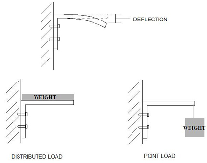 This calculator computes the displacement of a simply-supported circular plate under a uniformly distributed load. Notice that the deformation is axial symmetric and it is only a function of the radius. Hence, = 0.271728515625 mm 0.272 mm The beam calculator is a great tool to quickly validate forces in beams. Under the effect of temperature, the cement pavement becomes warped, which affects the deflection detection accuracy. (11.42) for the center point (maximum) deflection of the plate. affect the results as the clusters will be deactivated in the calculation phase. Lower roller driven power is: In the above formula: P Driven power (m KW) T Driven force moment (KN m) n 2 Lower roller rotation speed (r min -1 ), n 2 =2 V /d 2 (V is rolling speed) transmission efficiency =0.65-0.8. A uniform distributed load is a force that is applied evenly over the distance of a support. In the next section we focus on deriving the proper boundary conditions. Our online tools will help you select the most cost-effective products for your project, including joists, roof deck, floor deck, composite deck, and dovetail deck. The center deflection of rectangular plates with fixed at four edges and subject to the action of uniformly distributed loads is an important problem that has received considerable attention because of its technical importance. the deflection is WL^3/48EI.
When you click "Calculate Deflection" the tool will provide several engineering specifications such as the moment of inertia and yield strength to Beam Fixed at Both Ends - Single Point Load Bending Moment. The equation of motion for plates with stress-free and immovable edges are derived using modal analysis in conjunction with the expansion theorem. The deflection y of a uniformly loaded plate satisfies the differential equationt (1) V4^ = -4, where! Outrigger Load Point load = (1+2) x 100% = (50,000 + 23,500) x1 = 73,500kgs or 73.5t 4. The plate is under load w distributed along the diameter d 1. In construction, UDLs are preferable over point loads. For a pointed load at the centre of beam. 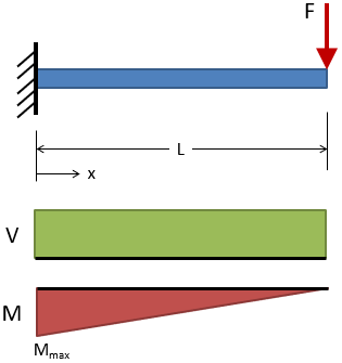 MATERIAL: THICKNESS: (T) WIDTH: (W) This method is based on the displacement--force (-F) curve function f(M)() obtained from the test, each slope of the curve was calculated using piecewise smooth function and the line segment in f(M)() elastic deformation area was searched by setting the minimum slope Just wondering the bending/deflection rate of 6061 1/2in thick aluminum plate is given 24in bar 4in wide, bolted on the left side with no support under the right side. This paper developed a calculation method to acquire the yield load P of bone plate during four-point bending test. Beam Deflection Calculators - Solid Rectangular Beams, Hollow Rectangular Beams, Solid Round Beams. Load The maximum load to be lifted 22,000kgs + Load 1,500kgs 3. Using the values of deflection we can calculate the bending stress. If you change any unit types or values please press SOLVE again. Use it to help you design steel, wood and concrete beams under various loading conditions.
  A _P 7^/(1
For a simply supported beam and uniformely distributed load, the deflection is 5WL^3/384EI. S = Simply Supported Edge: Shown as a dashed line on the edge that is simply supported. This calculator may give you a rough idea of the deflection of metal tubing, but it's not accurate enough to do any more than estimate it.
Calculate the deflection and bending moment at the centre of the plate assuming; (a) Simply supported conditions (b) Clamped edge conditions (v = 0.2; E = 2.1 x 10 7 kN/m 2) Solution FIXED EDGE RECTANGULAR PLATE - UNIFORM LOAD. Poisson's ratio =. Introduction:- If a beam carries uniformly distributed load or a point load, beam is deflected from its original position. Lateral deflection - Lateral deflection is the movement of a building structure horizontally resulting from loads. Calculator. Vulcrafts online design tools make it easier for you to specify our products, helping you increase project performance and reduce project costs. The load analysis of the rolling machine can be reference data for designing parts of plate rolls. Coefficient Ay - Coefficient Ay is the non-dimensional coefficient of lateral load term. CLEAR ALL clears all fields. Cantilever beam with point force at a random position. Solved Examples on the Analysis of Circular Plates. In order to solve this equation, however, we need to know the boundary conditions. Ground Type Ground comes in granular and cohesive types. My general go-to for these types of formulations is Roark's Formulas for Stress and Strain, 7th Edition. Downward force on the right side is 200lbs.  Solution: Refer to table 1(pg2) for allowable = L/240 = =1 inch since the Actual deflection (0.406in) is Less than the Allowable Result will be displayed. The use of the falling weight deflectometer (FWD) for detecting pavement voids is based on the principle that, under the same impact load, the deflection of pavements with voids increases significantly. Using The Deflection Calculator To begin, choose a profile type and part number. Reissner [1] presented the general linear equations for small deflection of a shallow segment of a thin, spherical shell.
M i = maximum bending moment, lbf.in/in or Nmm/mm. It looks like 1/4 thick steel would safely hold 4000 pounds in the center of a 24 inch span on a 72 inch wide plate. In plate theory, one generally distinguishes the following cases: 1. The ultimate bearing capacity from the plate load test q ult,bp = 335 kN/m 2. The motor power should be chosen properly. A circular plate of thickness (150 mm) and diameter 10m is subjected to a uniform lateral load of 10 kN/m 2. The force is concentrated in a single point, anywhere across the cantilever length. Simply select your extrusion profile, load distribution, and applied forces and get instant results for stress, deflection and safety factors. E = Youngs modulus of elasticity of the material in kN/sqm. The eects of geometric nonlinearities are discussed. F = Free Edge. 5. deflection of a constrained rectangular plate. From there input a length and the expected profile load. CLEAR ALL clears all fields. = poisson's ratio of plate material, assumed to be = T = 0 for coefficients. The fixed beam (also called clamped beam) is one of the most simple structures. For a rectangular plate clamped at the edges W is subject to the boundary In practice however, the force may be spread over a small area. Using The Deflection Calculator To begin, choose a profile type and part number. From there input a length and the expected profile load. When you click "Calculate Deflection" the tool will provide several engineering specifications such as the moment of inertia and yield strength to determine the deflection. A plate is generally regarded as a metal block with similar face dimensions (length, breadth, circular, etc.) So, plate load test is helpful for the selection and design the foundation. The plate deflection calculator is applicable to any circular ring or disk of constant cross section whose material obeys Hooke's law and deflects less than 10% of its major diameter. Solving this equation gives us the deflection of the plate; once we know the deflection of the plate we can calculate the bending and twisting moments and the stress distributions. This calculator calcultes the Maximum Deflection and Maximum Stress in a Simply Supported Rectangular Plate with a Concentrated Load. Enter your values as required and press SOLVE, your results will be displayed. Beams - Fixed at Applying a factor of safety of 3.0 against shear failure; Applying correction for sandy soil deposit and a footing of width 1.5m; q ult,f = q ult,bp x (Width of foundation)/ (Size of the base plate) = 335 x (1.5/0.6) = 837.5 kN/m 2. Select the mounting of the plate and the type of loading [2.1, 3.1, 4.1] Set the dimensions and loading and run the calculation [2.8, 3.9] If the deflection of the plate is higher than the half of its thickness, select paragraph [5.0, 6.0] for the calculation Deflection Calculator. The load on the plate is applied perpendicular to the center plane of the plate.
The deflection of a simply-supported plate (of corner-origin) with general load is given by w ( x , y ) = 1 4 D m = 1 n = 1 a m n ( m 2 a 2 + n 2 b 2 ) 2 sin m x a sin n y b {\displaystyle w(x,y)={\frac {1}{\pi ^{4}D}}\sum _{m=1}^{\infty }\sum _{n=1}^{\infty }{\frac {a_{mn}}{\left({\frac {m^{2}}{a^{2}}}+{\frac {n^{2}}{b^{2}}}\right)^{2}}}\sin {\frac {m\pi x}{a}}\sin {\frac {n\pi y}{b}}}
the shortest dimension of which is at least ten times its thickness. Flat Plates Stress, Deflection Equations and Calculators: The follow web pages contain engineering design calculators that will determine the amount of deflection and stress a flat plate of known thickness will deflect under the specified load and distribution.. Enter value and click on calculate. P = point load, lbf or N. i = length to width ratio coefficient. That said, Plates is equally applicable to those of greater thickness as deflection due to shear is included in the calculations. Deflection Calculator for Square Tubing. Lateral load - (Measured in Newton) - Lateral load is the live load that is applied parallel to the ground. Bearing Values BS: 8004 5. Force of load: 700 N Continuous load Force per mm: 0.05 N/mm Beam deflection from beams own weight: 3.9073716995894 mm Beam deflection from force at centre of the beam: 32.009364557265 mm Deflection from a continuous load supported by the beam: 7.1449474458181 mm The total deflection of this simply supported beam: 43.061683702672 mm Determining your machine's strength and rigidity is easy with Ventions t-slot aluminium extrusion deflection calculator. The formula is therefore close to useless as far as accuracy is concerned. The plate is simply supported on all sides. distributed loads. The assignment of a soil material to the clusters is required before generating the mesh. Restraining rotations results in zero slope at the two ends, as illustrated in the following figure. Calculate Deflection for Solid Rectangular Beams. The Allowable Bending Stress given the Plate Thickness explains the relationship involved between actual bearing pressure and width and thickness of plate is calculated using Allowable bending stress = (0.75* Actual bearing pressure *(Smaller Width of Plate-2* Distance from beam bottom to web fillet)^2)/(Plate thickness ^2).To calculate Allowable Bending Stress given the Plate For the least amount of deflection possible, this load is distributed over the entire length of the support. If the plate is simply supported then the MBM will be w*l/4 then equate it with the bending resistance of the plate material. Engineering Calculators Menu Engineering Analysis Menu. M A = - F a b 2 / L 2 (1a) where. I = Area Moment of Inertia in m^4. Assuming your plate is transversely loaded with a distributed load the maximum deflection with fixed edges is given by [math]y_m= frac{alpha p b^4 }{E t^3}math]&] Where: p is your pressure loading. b is the smallest plate edge dimension. t is the plate thickness. E is the modulus. P = Corner Supported by Post: Shown as a small square on the corner that is supported by a b = longest span length, in or mm. Introduction Several investigators have studied large deflection behavior of an empty spherical shell subjected to a point load Most previous analytical work on empty shells is based on a shallow shell theory. Pa kPa MPa GPa psi ksi lbf/ft^2 kgf/cm^2 atm bar mmHg inHg ftH2O. As a result of calculations, the bending moments M in the radial and tangential directions, angle of plate inclination i , deflection Y i and equivalent stresses i at the calculated point, lying on a circle with diameter D i are determined. Figure 1 - Plate Deflection Determined by Linear & Non-Linear Methods (1) If we consider the deflection of a glass plate, 1200 mm x 2500 mm, and 4 mm thick, four edge simply supported, and under a uniform load, Figure 1 shows the deflection calculated from both linear and geometrically non-linear plate theories within finite element analysis. An example would be a shipping crate on a forklift. This formula is only suitable for small deflections, i.e., on the order of the half thickness of the plate or less, and the formula gives something like 4 inches deflection under full vacuum. Toggle Menu This calculator computes the displacement of a simply-supported circular plate under a uniformly distributed load. It is to note that the analytical solution assumes a perfectly concentrated or a point load, whereas in the numerical models, the load was applied over a small area for practical purpose. The Navier solution for the rectangular plate simply supported on all sides and under a uniformly distributed load, q, as shown in Figure 1, is presented in Chapter 5 of Timoshenkos text. Calculate Deflection for Round Tube Beams. Many of the stress and deflection equations and calculators referenced L = Total length of the beam measured between centres of support in m. w = Load in kN ANSYS Solution.
Calculate Deflection for Solid Round Beams. Introduction A plate is a two-dimensional structural element, i.e., one of the dimensions (the plate thickness h) is small compared to the in-plane dimensions a and b. Bending of plates 1. Flat Plate Deflection Calculator | Flat Plate Stress Calculator The I= 78x10 6 mm 4 and value of E= 2.1x10 5 N/mm 2.Calculate the deflection at the centre of the beam and slope at the supports. The solution in series. p = 14.7 psi. Answer: If the plate is subjected to bending moments: Find the maximum bending moment. 1) When a column base resists only compressive column axial loads, the base plate must be large enough to resist the bearing forces transferred from the base plate (concrete bearing limit), and the base plate must be of sufficient thickness (base plate yielding limit). Hence, = 0.271728515625 mm 0.272 mm Stress The maximum bending moment occurs at the center of the plate, r = 0. (a)What is the Allowable deflection in inches, if the allowable deflection DL+LL due to is L/240; If the load applied represent the Dead and Live loads, determine if the beam deflection is acceptable? Use the ANSYS four node element shell63 for the model. Fixed supports inhibit all movement, including vertical or horizontal displacements as well as rotations. By this I assume you mean that all edges are fixed. The calculations included in Plates are primarily intended for the evaluation of A vertically downward point load equal to 100 kN/m is assigned to the one plate, while a vertically downward line load
This calculator calcultes the Maximum Deflection and Maximum Stress in a Fixed Edge Rectangular Plate with a Uniform Load. a = shortest span length, in or mm. The calculation of the main driven power of the plate roll bending machine is the key reference data for choosing the main motor. The power of the main motor can be 4. Mat size Mat size deducted from point load in 3 (in kNs) / (Soil type value 2) 721.0kNs / 300KN/m2 = 2.40 m2 To calculate safe bearing capacit y suitable factor of safety is applied. E = 30 x 10^6 psi (Young's modulus) t = 0.25 in. Enter your values as required and press SOLVE, your results will be displayed. M A = moment at the fixed end A (Nm, lb f ft) F = load (N, lb Beam Loads - Support Force Calculator - Calculate beam load and supporting forces. These formulations assume a flat plate with straight boundary conditions and constant thickness. 2. Beam Design is one of the most common cases in machine design, many parts of the machine such as shaft, structure, etc, can be assumed, designed, and calculated as a beam. The plate has two planes of symmetry, so we model just one quadrant and apply appropriate boundary conditions.